Fuse type Isolating Switch
Fuse type Isolating Switch
The product can be installed with DC and AC fuses to protect DC and AC systems
Application
UPS for the power supply of computers and servers
Telecommunication power supply
Metering and lighting module applications
Switchboards
Capacitor banks
General fuse for power supply networks
Power supply and generation fuse protection
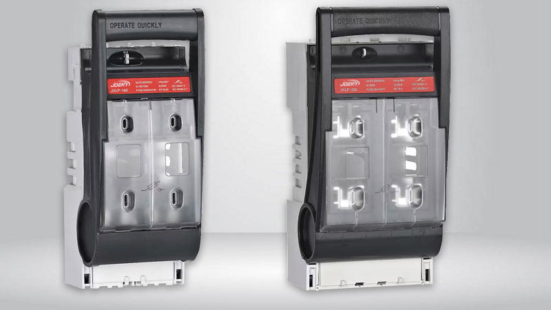
JXLP-160/250 series fuse type isolating switch
Product Description
JXLP series fuse-type isolating switches works with NH00 and NH01 type fuses. Has aworking voltage range of 0-500V DC and 0-690V AC with a maximum current of 800A. The working current varies according to size of fuse used.
Model and meaning

Normal operating conditions and installation conditions
The ambient air temperature should not be higher than +50℃ and not lower than -5℃.
Humidity: When the maximum temperature is +50°C, the relative humidity of the air does not exceed 50%. Higher relative humidity is allowed at lower temperatures, such as 90% at 20°C. Special measures should be taken against occasional condensation due to temperature changes.
The pollution level of the surrounding environment is level 3.
The switch should be installed in a place without significant vibration away from hazardous and flammable materials.
Has an IP30 rating when closed and IP20 rating when open.
The relationship between switches and fuses
Agreed heating current (A) | Fuse link model | Rated working voltage (V) | Optional fuse (A) |
Max 160 | NT00 RT16-00 | 1-220VDC | 4、6、10、16、20、25、32、35、40、50、63、80、100、125、160 |
220-500VDC | 4、6、10、16、20、25、32、35、40、50、63、80、100、125 | ||
220-400VAC | 4、6、10、16、20、25、32、35、40、50、63、80、100、125、160 | ||
400-690VAC | 4、6、10、16、20、25、32、35、40、50、63、80、100、125 | ||
Max 250 | NT1 RT16-1 | 1-500VDC | 80、100、125、160、200、225、250 |
220-400VAC | 80、100、125、160、200、225、250 | ||
400-690VAC | 80、100、125、160、200 |
Switch technical parameters

The rated voltage of the auxiliary switch is AC 380V, the agreed heating current is 5A, the usage category is AC-15, and the rated working power is 300VA.
Structure
The switch is composed of a base, a cover and a contact bridge. The fuse is installed inside the cover. The cover can rotate in a fan shape along the support. It has a large electrical isolation distance to meet the requirements of the isolating switch. The cover can be easily removed from the base. Removable, making it easy to install and replace the fuse link.
There are two sets of mounting holes on the base, which can meet the installation requirements in various switch cabinets and on panels. On both sides of the switch, auxiliary contacts can be installed as needed to send signals indicating the opening and closing status of the switch.
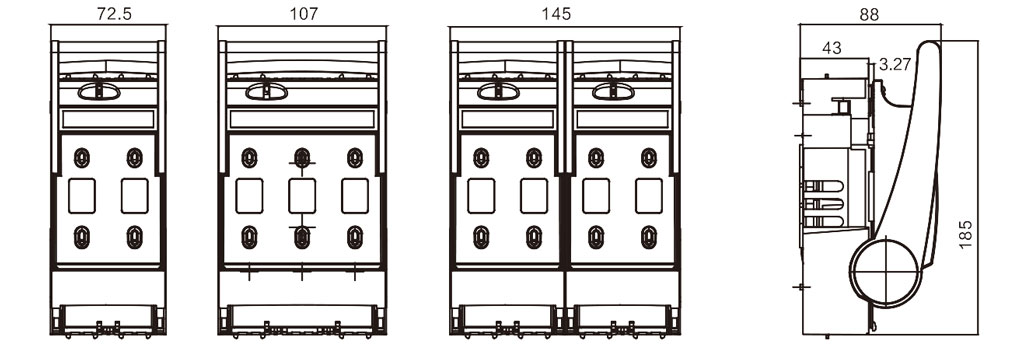
Shape and installation dimensions
JXLP-160 External dimension drawing
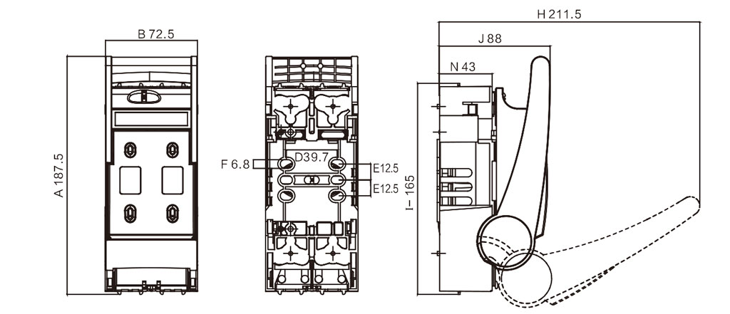
JXLP-160 Installation dimension drawing
JXLP-250 Installation dimension drawing
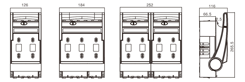
JXLP-250 Installation dimension drawing
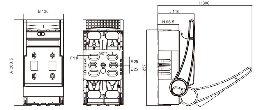
Size | Specifications | |
160A | 250A | |
A | 187.5 | 268.5 |
B | 72.5 | 126 |
D | 39.7 | 57.3 |
E | 12.5 | 25 |
F | 6.8 | 11 |
H | 211.5 | 300 |
J | 88 | 116 |
I | 165 | 237 |
N | 43 | 66.5 |
Use and maintenance
Before installation, check whether the switch is intact and can be operated flexibly;
Working conditions should comply with regulations 3.1~3.5;
The switch should be regularly maintained and adjusted to remove dirt and keep clean so that the contacts can work in good contact condition;